Introduction
This guide walks through building a Landy Gauge from scratch. You’ll need basic soldering skills and access to a 3D printer (or a printing service).
What You’ll Need
Main Gauge
- Waveshare ESP32-S3 1.85" Round Touch or non touch LCD module
- Custom gauge PCB (KiCad files provided)
- Components as per the BOM
- 3D printed case
Expansion Board (Optional)
- Custom expansion board PCB
- MCP23017 I/O expander
- Components as per the BOM
- 6-wire cable (recommended: 500mm max). This is actually a Bambu labs AMS interconnect cable.
- 3D printed case
Sensors
- EGT: K-type thermocouple. These are pretty standard. I used a generic K-type thermocouple from Amazon.
- Boost: MAP sensor (0.5V–4.5V output). There are many options but I went with a FEDLDM187 which is used by Renault
- TPMS: BLE tyre pressure sensors (4x). Any generic BLE sensor will work but you might need to change the format string used for reading. The specific ones I went for are AIYATO BLE TPMS from Amazon
Assembly Steps
1. PCB Assembly
I had all my PCB manufactured by PCBWay in China. It was fast and cheap with great results. I had them populate the boards for the supply and expansion board as they use SMD parts. The expansion board i did just as a desktop test board so had screw terminals for connections. My intension was to produce a smaller specific board for the final gauge but it didn’t turn out to be a high priority. I asked PCBWay not to populate the screw terminals so that I could solder wires directly to the connections to use in the Landrover. You could keep the screw terminals in the car but should seal the screw with some wax to stop them vibrating loose. A Landroiver vibrates a lot so I went for the solderd connections. The Fan Relay PCB layout can be improved a lot and I forgot to put pads on the vias I used for wire links to be able to use a single sided board. It also uses a thicker Cu layer to handle the current. If you go the fan control route don’t go with the layout as is…
2. WaveShare Preparation
The Waveshare boards are great but they do have one design choice that makes their use difficult. They have put all the connections going out the sides of the board with rightangle connectors. It would have been much better if they had used verticle connectors. The problem with the 52mm gauge is it doesn’t have room for the connectors and cables sticking out the side. Fortunately the speaker connection is shallow enough that it just fits with a cut out in the case. The I2C and IO connectors however don’t.
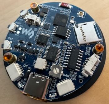
The solution is to replace the right angle connectors with vertical versions. This reverses the pin out of the connector but the gauge Supply PCB flips it back again letting you use a 1-1 cable.
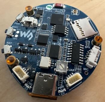
The challenge is that the Waveshare has the LCD fitted which is temperature sensitive so you need to be a bit careful when removing and reflowing the new conectors. I place the waveshare LCD down on a block of metal to keep the LCD cool as I used a hot air gun to remove the connector. A further complication once you have the connectors swapped is the cables are tiny. Making up cables needs, at least for my 66 year old eyes, a magnifing setup, tweezers and a lot of swearing. As a consequnce I now don’t replace the conector I just remove the right angle connector and solder the cables that come with the display directly to the PCB. A bit of resin over the soldered joint holds it all in place. The final step is to put a power connection on to the Waveshare. The LandySupply board provided a protected 5V supply that is fed to the Waveshare after the protection diode from the existing USB-C connection. The design lets you plug in a USB-C cable while the 12V supply is still connected without damaging either the gauge or the attached computer. This permits insitue reprogramming or monitoring of the gauge. Use a two pin JST plug and connect the positive wire to the end of the Waveshare protection diode, D3 at it’s connection with R3, being careful not to short both ends of the resistor. The negative (GND) connects to the ground pad of the I2C connector (which you have removed) You now have a Waveshare display with three cables attached one 4 way for I2C, a second 4 way for IO and a 2 way for the power. These need to be about 50mm long. The connector for the I2C and IO come with the Waveshare and you can buy made up cables for the two way from Amazon. I recomend doing that rather than buying a connector kit. Been there done that…
A note for tinkerers - Connecting the supply in this way creates a safe supply for the Waveshare but it does bypass the charging facility built in to the Waveshare. If you want to use the backup battery with charging from 12V as well as from USB-C then you can connect to the other side of D3. The 12V will now charge the optional backup battery as well but you MUST disconnect the 12V supply from the gauge before plugging in the USB-C or you can potentially damage your computer. Given that my Landrover has a big old lead acid starter battery the optional waveshare battery is a bit pointless.
3. Case Printing
Print the gauge case using the provided OBJ files. Recommended settings:
- Material: PETG with default setting. Other materials such as PLA work fine too.
- Layer height: 0.16mm
- Infill: 20% The back needs support and benifits from using an interface layer for clean removal. The bezel can be printed in teh same material for a one time assembly. If repeated assemble/disassembly is anticipated use a firm TPU (like Bambu TPU for AMS) for the bezel. The Button Plug also works best in TPU for AMS.
The expansion board case can be printed in any material. I used PA6-GF as I used this for the Fan relay box that lives in the engine bay.
4. Firmware Flashing
See the Firmware page for build and flash instructions.
5. Sensor Installation
Expansion Board Installation
Wiring
The expansion board connects to the main gauge via I2C:
- SDA, SCL, VCC (3.3V), GND
- Maximum recommended cable length: 500mm
- I2C speed: 100kHz (for cable reliability)
Vehicle Signal Connections
Connect vehicle signals to the expansion board inputs. All inputs are active-high, optically isolated:
| Input | Connect to |
|---|---|
| IO1 | Ignition switched 12V |
| IO2 | Sidelights circuit |
| IO3 | Cooling fan low speed relay |
| IO4 | Cooling fan high speed relay |
| IO5 | Coolant level warning |
| IO6 | Dipped beam circuit |
| IO7 | Full beam circuit |